Environmental Impacts of Solar-Photovoltaic and Solar-Thermal Systems with Life-Cycle Assessment


School of Engineering, Macquarie University, Sydney, NSW-2109, Australia
*
Author to whom correspondence should be addressed.
Energies 2018, 11(9), 2346; https://doi.org/10.3390/en11092346
Submission received: 7 August 2018
/
Revised: 31 August 2018
/
Accepted: 1 September 2018
/
Published: 5 September 2018
(This article belongs to the Section A: Sustainable Energy)
Abstract
:The demand for clean energy is strong, and the shift from fossil-fuel-based energy to environmentally friendly sources is the next step to eradicating the world’s greenhouse gas (GHG) emissions. Solar energy technology has been touted as one of the most promising sources for low-carbon, non-fossil fuel energy production. However, the true potential of solar-based technologies is established by augmenting efficiency through satisfactory environmental performance in relation to other renewable energy systems. This paper presents an environmental life-cycle assessment (LCA) of a solar-photovoltaic (PV) system and a solar-thermal system. Single crystalline Si solar cells are considered for the solar PV system and an evacuated glass tube collector is considered for the solar thermal system in this analysis. A life-cycle inventory (LCI) is developed considering all inputs and outputs to assess and compare the environmental impacts of both systems for 16 impact indicators. LCA has been performed by the International Reference Life Cycle Data System (ILCD), Impact 2002+, Cumulative Energy Demand (CED), Eco-points 97, Eco-indicator 99 and Intergovernmental Panel on Climate Change (IPCC) methods, using SimaPro software. The outcomes reveal that a solar-thermal framework provides more than four times release to air () than the solar-PV (), and the outputs by a solar-PV system to soil () and solid waste () are about one third that of solar-thermal. The findings also depict that the solar panels are responsible for the most impact in the considered systems. Moreover, uncertainty and sensitivity analysis has also been carried out for both frameworks, which reveal that Li-ion batteries and copper-indium-selenium (CIS)-solar collectors perform better than others for most of the considered impact categories. This study revealed that a superior environmental performance can be achieved by both systems through careful selection of the components, taking into account the toxicity aspects, and by minimizing the impacts related to the solar panel, battery and heat storage.
1. Introduction
The accelerating growth of the world economy and the exponential rise of the global population have resulted in an increasing demand for traditional fossil-fuel-based power production, resulting in the emission of record levels of greenhouse gas (GHG) [1,2]. This burning of fossil fuels usually causes significant environmental degradations such as air pollution, global warming, ozone-layer depletion, acid rain, climate change and many more [3,4]. Therefore, researchers have been trying to develop alternative sustainable-energy technologies to overcome the challenges of the energy crisis and its environmental impact [5,6]. Due to the growing demand for renewable-energy sources in the last decade, photovoltaic (PV) technologies are getting considerable attention because of their paramount potential for large-scale sustainable energy generation with higher efficiency and a superior environmental profile with smaller carbon dioxide (CO) emissions [7,8,9,10]. It is generally considered that solar technologies have smaller environmental effects than conventional power generating units, but between solar-PV and solar-thermal systems which one is more environmentally friendly has not been explored and compared considering the impacts from each elements production, transportation, installation, operation and end-of-life recycling.
The research goal of this project is to assess the environmental effects of solar-PV and solar-thermal frameworks by a systematic life-cycle assessment (LCA) approach and compare the findings for a better informed choice. Over time, there have been significant advancements achieved by various research groups in the efficiencies and economic viabilities of PV technologies like solar-PV systems and solar-thermal systems [11,12,13]. Several research studies have been done in calculating the effects of a single element of solar technologies like PV panels [14,15,16,17], batteries [18], solar-thermal collectors [19], etc. Some others carried out country-based LCA research [20,21,22,23,24,25,26,27,28] to assess the impacts of solar technologies; they have not considered a global database, which is required for the consistent global practice of LCA [29] and global policy development [23]. Moreover, there are separate LCA analyses to find the hazards of solar technologies that directly affect the human body [30,31,32,33], but they have not measured the rate of energy used from fossil-fuel-based sources in manufacturing solar-PV and solar-thermal systems. In this study, a literature review on previous studies of LCA-based solar-thermal and solar-PV systems and the summary is highlighted in Table 1 and Table 2, respectively. However, very few studies in the open literature assessed and compared the environmental impacts for the individual parts of both frameworks, which is required to identify the problematic elements and to replace them by their equivalent environmentally-friendly options. Therefore, given the remarkable role that solar technologies have to play in reducing global greenhouse gas (GHG) emissions, it is necessary to investigate the environmental profiles of both solar PV and thermal systems considering each element of the system to understand their full potential.
Herein, the ecological impacts incurred by solar-PV and solar-thermal systems are assessed and compared by LCA approach for each of the elements like solar collector, battery, converter, inverter, power meter, breaker, flow meter, valve, pump, heat transfer fluid tank etc. In the LCA analysis both systems are considered for a small residential area. The amount of GHG emissions and fossil-fuel-based energy consumption by each element of both frameworks is also estimated. Moreover, the sensitivity analysis of the considered systems is conducted by varying the PV panels and the battery storages to track the best option in terms of their effects on the environment. Therefore, the key contributions of this paper can be summarized as follows:
- Development of a comprehensive life-cycle inventory (LCI) considering the inputs and outputs of solar-PV and solar-thermal systems.
- Assessment of the environmental impacts for elements of both frameworks from a “cradle to grave” scheme for 16 impact indicators.
- Comparison of the effects from both systems.
- Quantification of the greenhouse gas (GHG) emissions from both systems throughout their lifetime.
- Evaluation of the amount of fossil-fuel-based power consumption during the manufacturing of elements, installation and operation of the systems, and the waste-management period.
- Accomplishment of sensitivity and uncertainty analysis for both systems.
The current study is different from some of the previously reported studies [3,36,37,38] and provides additional information on the impacts associated with each of the elements like PV panel, valve, battery, converter, controller, flow meter etc. in both solar-PV and thermal systems, which identifies the critical materials and stages; it is anticipated that by replacing the hazardous materials the environment can be escaped from long-term dangerous emissions. In the light of the above, the rest of the paper is arranged as follows. The materials and methods are briefly described in Section 2. The results and discussions to reveal the environmental performances of solar PV and thermal systems are presented in Section 3, and concluding remarks on the research outcomes and recommendations are highlighted in Section 4.
2. Materials and Methods
2.1. Solar-PV and Solar-Thermal System Overview
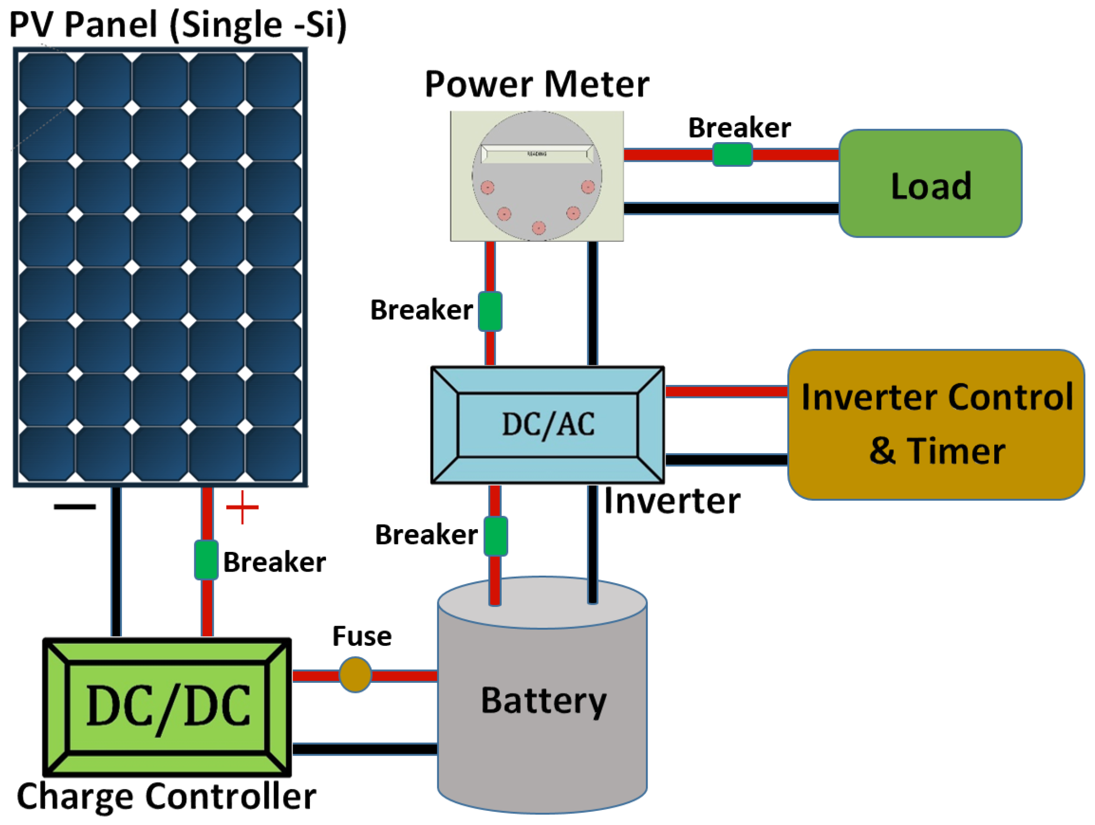
The solar-PV system consists of a mono-crystalline PV panel, DC-to-DC charge controller, DC-to-AC inverter, power meter, breaker and battery (Figure 1). The PV panel generates DC electricity which is controlled by the charge controller (DC/DC) to obtain a regulated DC output. The controlled DC current is then stored into the battery. The DC output from the battery is inverted to AC by the DC/AC inverter. A power meter is utilized to measure and record the flow of electricity.
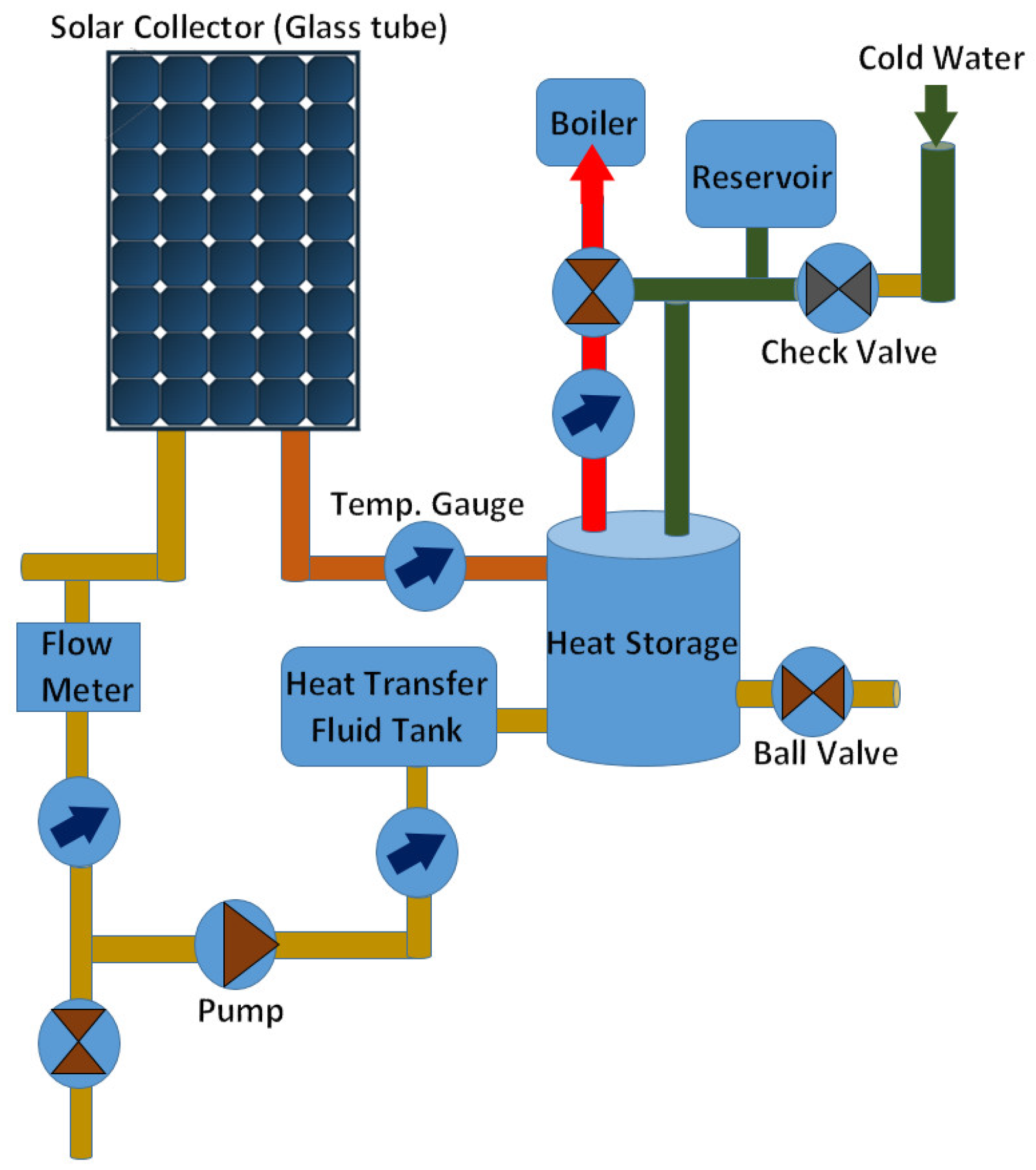
Figure 2 shows the schematic framework of the solar-thermal system. It consists of a solar collector, flow meter, pump, heat transfer fluid (HTF) tank, ball and check valve, heat storage, temperature gauge, boiler and reservoir. The PV collector harvests solar energy and converts it into heat, which is utilized to warm the cold water. The temperature gauge and flow meter measure the water temperature and flow rate, respectively. The pump is used for circulating the water throughout the system. The heat storage is between the boiler, the HTF tank and the solar collector. The boiler is a vessel where water is heated.
2.2. Life-Cycle Assessment Method
The main aim of this research is to find the environmental impacts of solar technologies like solar-PV and solar-thermal systems, and compare their effects on the environment using sixteen impact indicators. For that reason, a well-ordered LCA method is used. LCA is a very effective approach for evaluating the environmental hazards of any device or system [39,40,41]. LCA has been widely used in impact estimation, sensitivity analysis and sustainability testing [42,43,44,45,46]. This LCA has been accomplished maintaining the ISO (International Organization for Standards) standards 14040:2006 and 14044:2006 [47,48]. In this study, SimaPro version (SimaPro, Amersfoort, The Netherlands) was used to evaluate the ecological threats of solar technologies. Herein, LCA is carried out by creating a life-cycle inventory (LCI) considering all of the elements for both solar technologies. The following four basic steps are maintained in LCA analysis:
- Goal and scope definition, where the LCA objective is highlighted and the boundaries are determined following ISO 14040 [48].
- Life-cycle inventory, where the energy, material and emission-based input–output flows are assembled following ISO 14041 [47].
- Life-cycle environmental-impact evaluation, where impacts are assessed for sixteen effect indicators following ISO 14042 [47].
- Impact outcome interpretation, where obtained effects are annotated and examined with the objective of the LCA, following ISO 14043 [48].
The major LCA steps are explained in the following sections to highlight the LCA approach carried out in this work.
2.2.1. Goal and Scope Definition
The first step of LCA is goal and scope definition. The main objective of this LCA is to assess and compare the ecological hazards of solar PV and thermal systems. The LCA is carried out considering both mid-point (cradle-to-gate) and end-point (cradle-to-grave) aspects for both of the frameworks [46,49]. Therefore, the total LCA takes into account all of the life-cycle stages for both systems such as raw-material extraction, key element production, transportation, framework installation, and waste management. The functional unit of the LCA is considered as 1 kWh of energy production, which determines the reference flow rates [39,41].
2.2.2. Life-Cycle Inventory
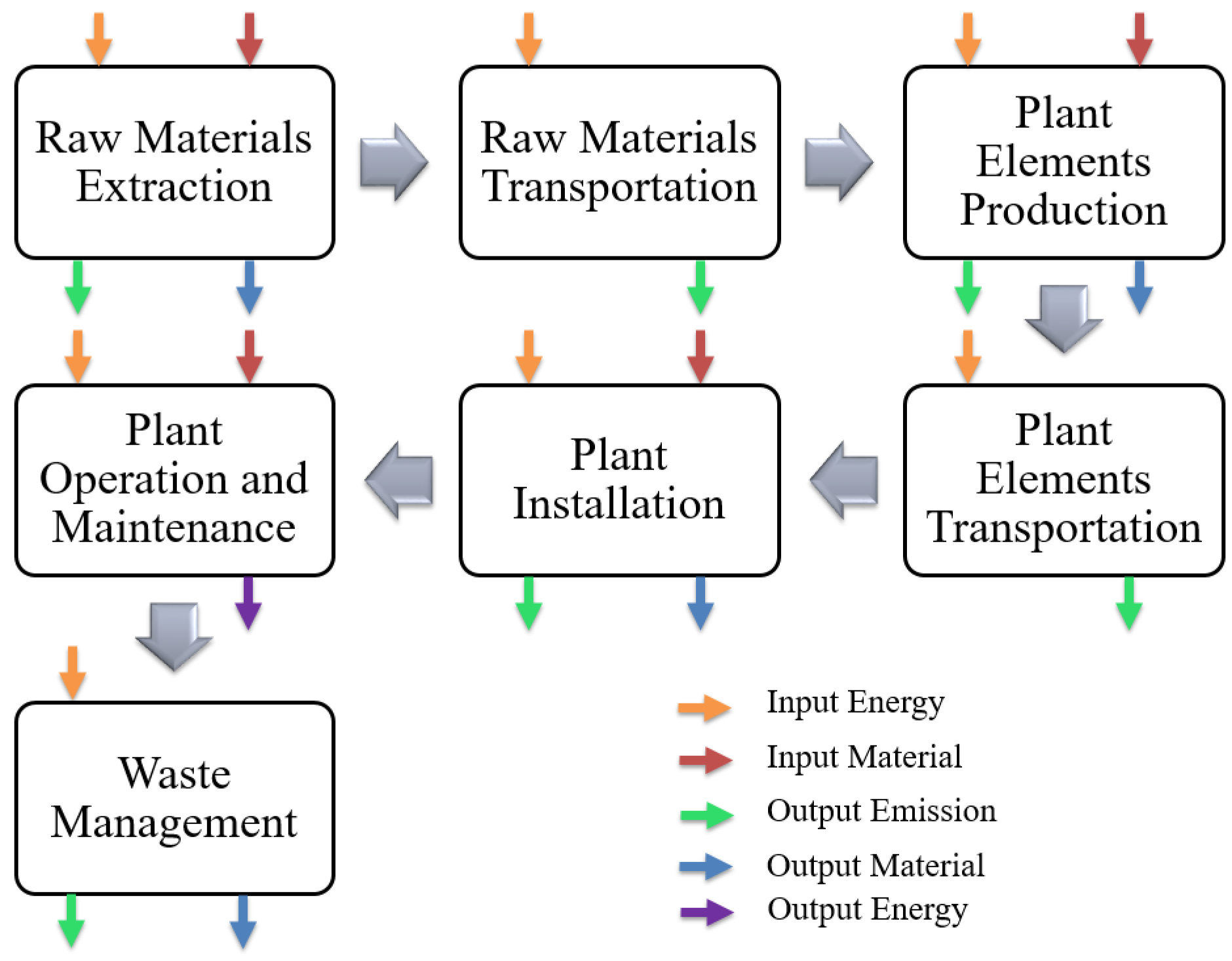
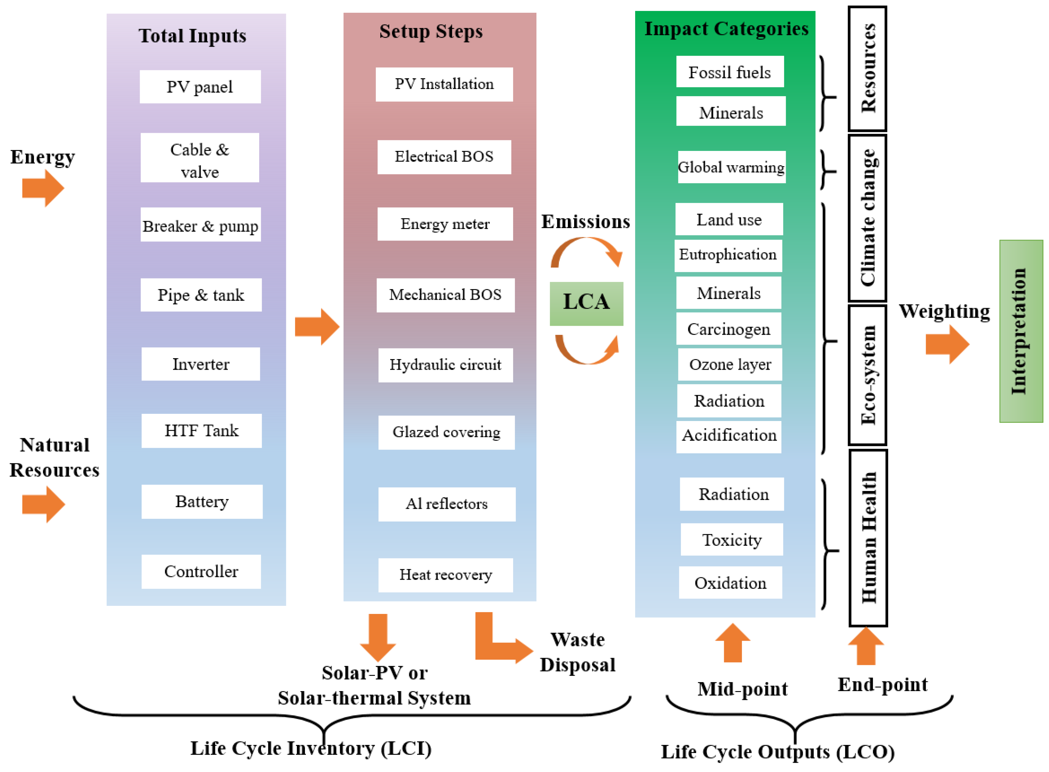
The formation of the life-cycle inventory is the second step of LCA. The input resources like raw materials and energies and the output emissions per unit process are considered in assembling the LCA inventory. Figure 3 shows the step-by-step energy and material flows for both systems. Both solar technologies follow the same steps in their lifespan such as raw-material extraction from mines using resources, raw-material transportation to the plant location for manufacturing key materials, key-material production at the plant, transportation of the produced materials to the solar plant area, installation and operation of the plant, and finally the end-of-life waste management. At each step, there are input and output flows as marked in the figure. We created a comprehensive life-cycle inventory for both frameworks. Figure 4 shows the system boundary considered in this research. The Ecoinvent database [50,51] is used to gather the input and output flows, as it has international industrial and commercial data for material production, transportation, energy consumption etc. [29,50,51]. Table 3 shows the data source for each of the key elements of the frameworks. An assembly is formed using all the unit processes of the solar-PV system, which is then used to assess the individual impacts of each process element. Likewise, another assembly is built using all unit processes of the solar-thermal system to find the effects from each element.
2.2.3. Life-Cycle Impact Evaluation
Life-cycle impact evaluation is the third step of the LCA analysis. The rate of reference flow is considered for the one functional unit (1 kWh). Impacts were assessed by using the SimaPro software for both frameworks. The International Reference Life Cycle Data System (ILCD) method is utilized in evaluating the effects. This approach considers the inputs from the raw-materials extraction to manufacturing, transportation and usage (cradle-to-gate or mid-point) [30], and gives outputs for sixteen impact indexes. It gives potential environmental impacts under major effect indicators like global warming, climate change, land use, toxicity, acidification etc. The cradle-to-grave (end-point) LCA analysis was carried out by the Impact 2002+ approach [52] under fourteen impact categories: carcinogens, non-carcinogens, respiratory inorganics, ionizing radiation, ozone-layer depletion, respiratory organics, aquatic ecotoxicity, terrestrial ecotoxicity, terrestrial acid, land occupation, aquatic acidification, aquatic eutrophication, global warming and non-renewable energy, which are further subdivided into four major indicators, namely human health, ecosystem quality, climate change and resources. The Raw Material Flows (RMF) method tracks the mass flow of all inputs and outputs based on adding all the elementary flows available in the Ecoinvent 2.0 database [53]. This RMF method is utilized to find and compare the input materials and output emissions of the systems. The Cumulative Energy Demand (CED) approach is employed to calculate fossil-fuel-based energy usage amounts for both of the considered frameworks, as this approach has been extensively used in assessing different sorts of fuel intakes throughout the lifetime of a unit [54]. CED considers various fuel inputs such as fossil fuels, renewable, nuclear, biomass and embodied energy for the overall lifespan of both systems [55,56]. It is important to realize the consumption of carbon-based-fuels to replace them by the renewable sources for better environmental performance. Moreover, the Intergovernmental Panel on Climate Change (IPCC) approach is employed to assess the greenhouse gas emission rate. The IPCC approach reveals the climate change factors by the considered systems with a time frame of 100 years. This method usually considers hazardous gas emissions like carbon dioxide, methane, nitrous oxide, etc. [57]. Uncertainty analysis has been conducted by the ILCD method to check the sustainability for the environmental-impact indicators of the LCA analysis and to investigate the probability distribution of both systems following the method described in [10,30]. Finally, sensitivity analysis is accomplished using ILCD method considering different PV panels and battery storages to examine their effects.
2.2.4. Life-Cycle Impact Interpretation
The life-cycle impact interpretation is the final stage of the LCA. The impacts are assessed, compared and interpreted in terms of the main factors responsible for environmental effects of both solar PV and thermal systems. Moreover, logical judgments are given based on uncertainty and sensitivity analysis.
3. Results and Discussion
3.1. Environmental Profiles of the Solar-PV System
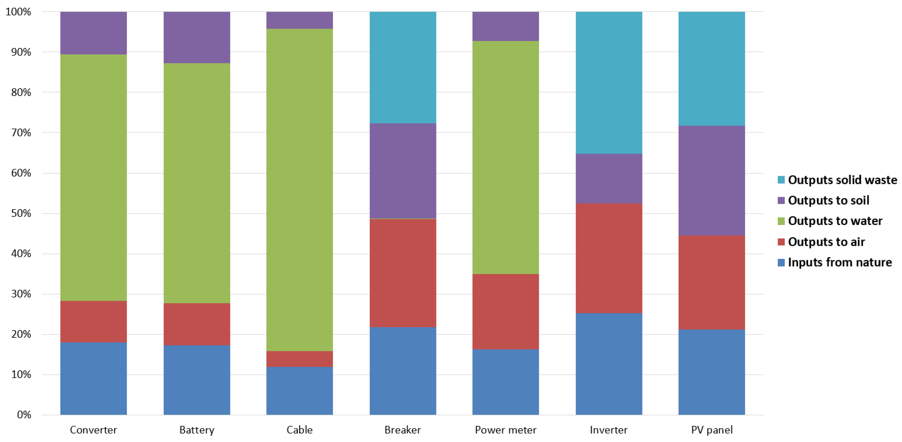
The overall inputs from nature and outputs to soil, water, air and solid waste scenarios for each element of the solar-PV system are assessed by the Raw Material Flows (RMF) approach [53]. This approach gives output considering the raw material and emission-based mass flow by adding all elementary flows. The life-cycle inputs and outputs of the elements of solar-PV system such as PV panel, inverter, power meter, breaker, cable, battery and converter are evaluated considering step-by-step energy and material flows by the RMF method.
The obtained results are presented in Figure 5 for better understanding and comparison. Amounts are obtained in kilograms and the total amount of each element like converter, battery, cable etc. is set at . In case of the PV panel, it is clear from the figure that it intakes about from nature during production and releases equally to air, soil and solid waste (about ), but there is no direct release into water throughout the lifetime of the PV panel. On the contrary, the converter, battery, cable and power meter of the solar-PV framework release a higher output to water, whilst the inverter, breaker and PV panel release more output as solid waste (landfill). Therefore, the end-of-life recycling of these key parts is essential to overcome for the problems associated with their release into water and soil.
The environmental impacts caused by each element of the solar-PV framework are depicted in Figure 6, found by the ILCD method [30]. The maximum effects occurred for the climate change, ozone depletion, human toxicity, photochemical ozone depletion, acidification, terrestrial and marine eutrophication, and water resource depletion impact categories by the PV panel. On the other hand, the highest impacts from the battery were for the effect indicators of mineral, fossil and renewable resource depletion, land use, and freshwater eutrophication. As it is not possible to build a battery without chemicals, and these chemicals are mostly responsible for the harmful emissions and other effects of the battery, researchers should rethink the use of environmentally-friendly materials without considering efficiencies. Furthermore, the power meter is mostly responsible for ionizing-radiation-based impact because it carries much energy to ionize electrons from atoms during operation. This radiation is a risk for the human body as it can affect DNA and can damage living cells. Therefore, future research should be directed toward developing an energy meter with the smallest ionizing-radiation-based impact.
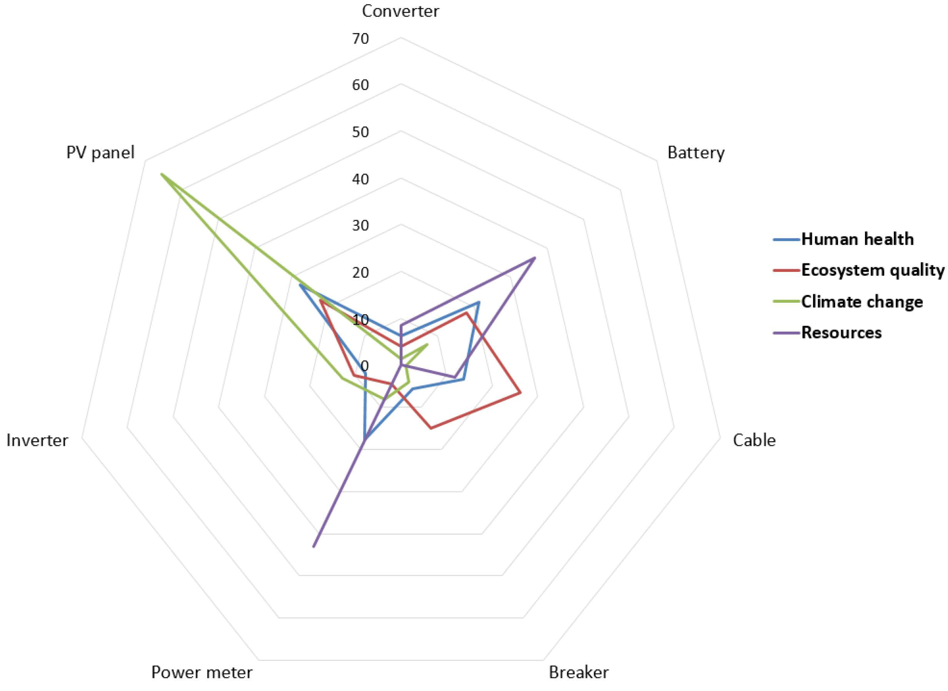
The results from end-point LCA analysis of the solar-PV system using the Impact 2002+ approach [52] are depicted in Figure 7. The PV panels are mostly responsible for affecting human health and climate change, whereas the battery mostly affects resources. The hazardous fluids used to transfer heat in solar modules are mostly responsible for the high impacts like toxicity and acidification, which is still required to be sorted out by the researchers.
3.2. Environmental Profiles of the Solar-Thermal System
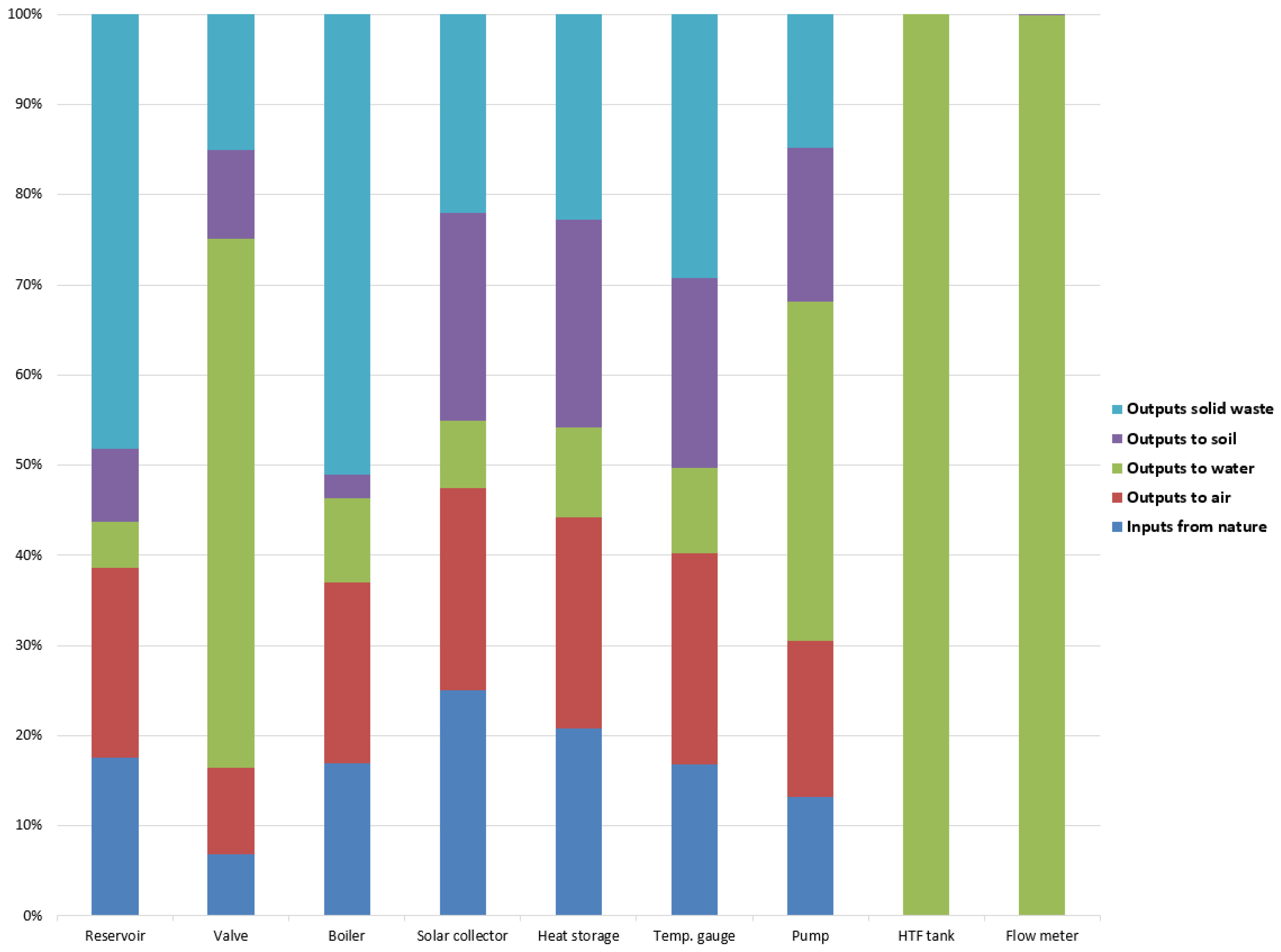
In this section, the life-cycle environmental hazards of a solar-thermal system are highlighted. The total input–output scenarios for each part of the solar-thermal system are evaluated by the RMF method [53]. The life-cycle input–output rates of the solar-thermal framework are depicted in Figure 8. The solar collector takes of its total inputs from nature and others from other non-nature-based sources. It releases about to solid waste, about to the soil, about to water and about to air. On the other hand, the boiler released mostly solid waste (about ). Almost of its inputs comes from nature. However, the pump and valve of the solar-thermal system emitted more output to water, whilst the boiler, reservoir and temperature gauge emitted significant outputs as solid waste. Moreover, the solar collector and heat storage released mostly to the air. However, the HTF tank and flow meter are totally discharged into water at the end-of-life. This happens because in the considered case these two parts have not been recycled.
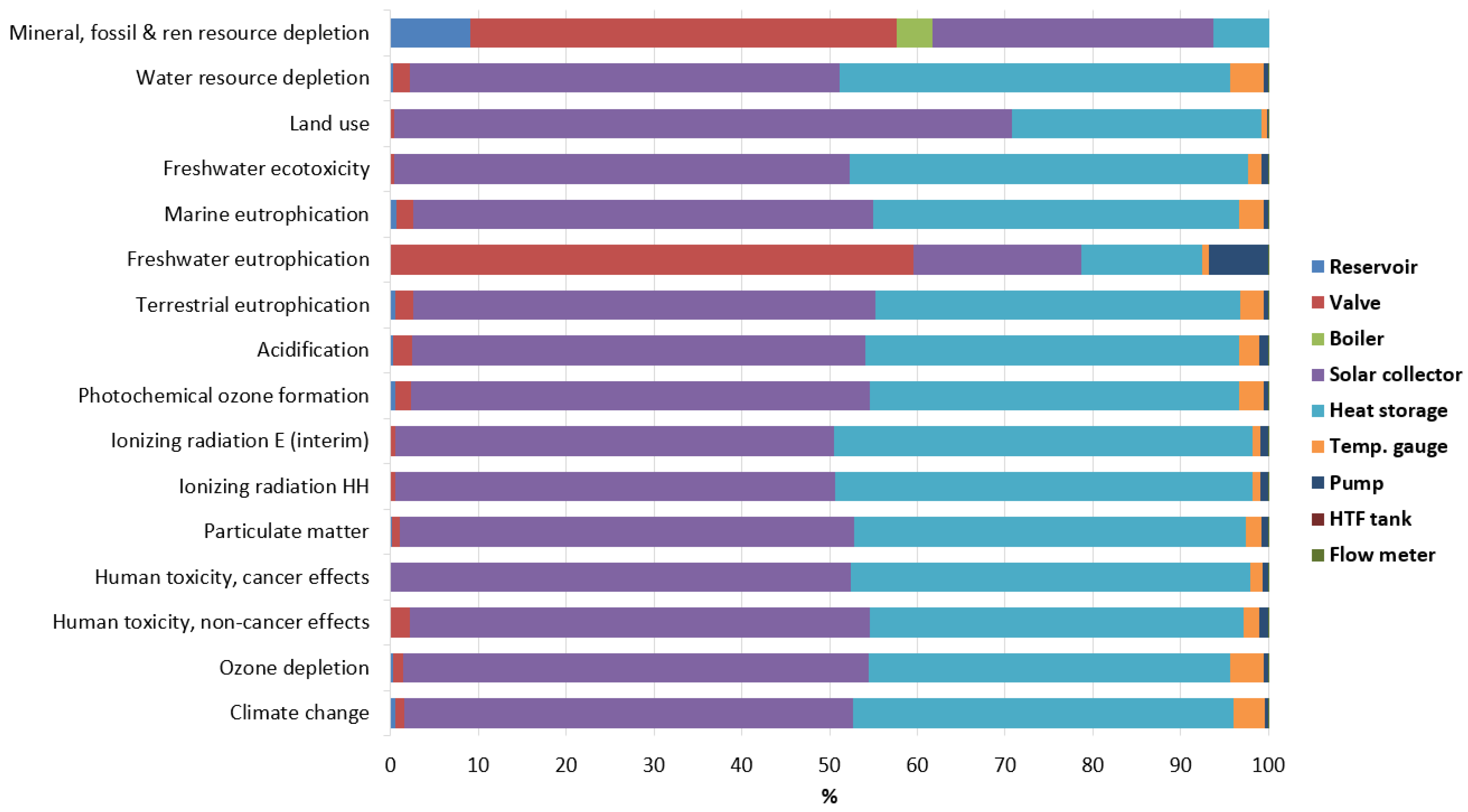
The cradle-to-gate (mid-point) environmental effects of each part of the solar-thermal system are highlighted in Figure 9, obtained by the ILCD approach [30]. Among sixteen impact types, the highest impacts are occurred to climate change, ozone depletion, human toxicity, acidification, terrestrial eutrophication, ecotoxicity, water resource depletion and land use from the solar collector. However, the maximum hazards from the valve were to freshwater eutrophication and mineral, fossil and renewable resource depletion. Furthermore, the other parts of the framework showed minor impacts. Overall, most of the impact from the solar-thermal system occurred for the solar collector and heat storage (about for the 14 impact categories) because of the use of hazardous materials and chemicals in their manufacturing, operation and recycling.
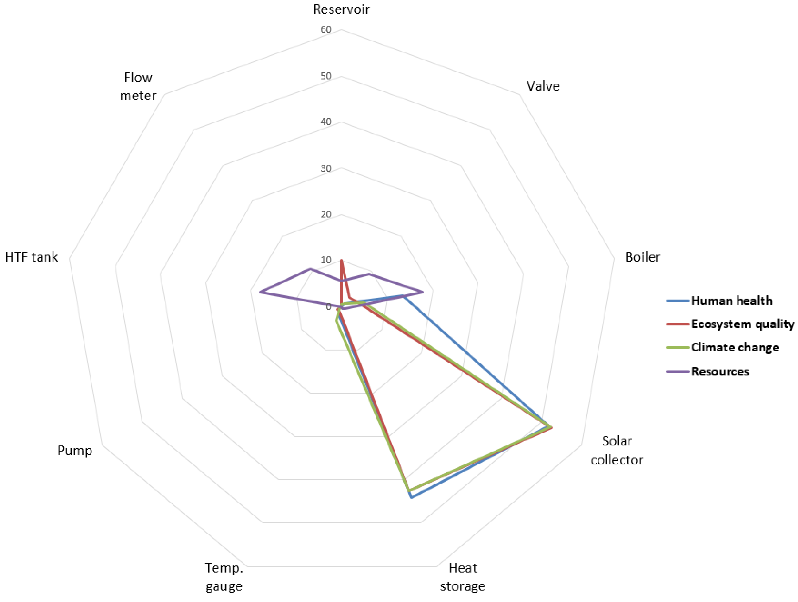
The end-point LCA analysis of the solar-thermal system was done by the Impact 2002+ method [52]. The end-of-life results depicted in Figure 10 reveal that the solar collector and the heat storage are the critical components in terms of the environment, as they are mostly responsible for damaging the ecosystem, climate and human health. Moreover, the boiler and HTF tank affect resources to a great extent in comparison with other parts of the framework.
3.3. Impacts Comparison between Solar-PV System and Solar-Thermal System
The input–output comparison between the solar-PV system and the solar-thermal system is highlighted in Table 4, which shows that a higher input from nature is taken by the solar-thermal system than by the PV system. However, the outputs to the air, soil and solid waste are a greater from the solar-thermal system than from the PV system, whilst outputs to water are mostly by the PV system.
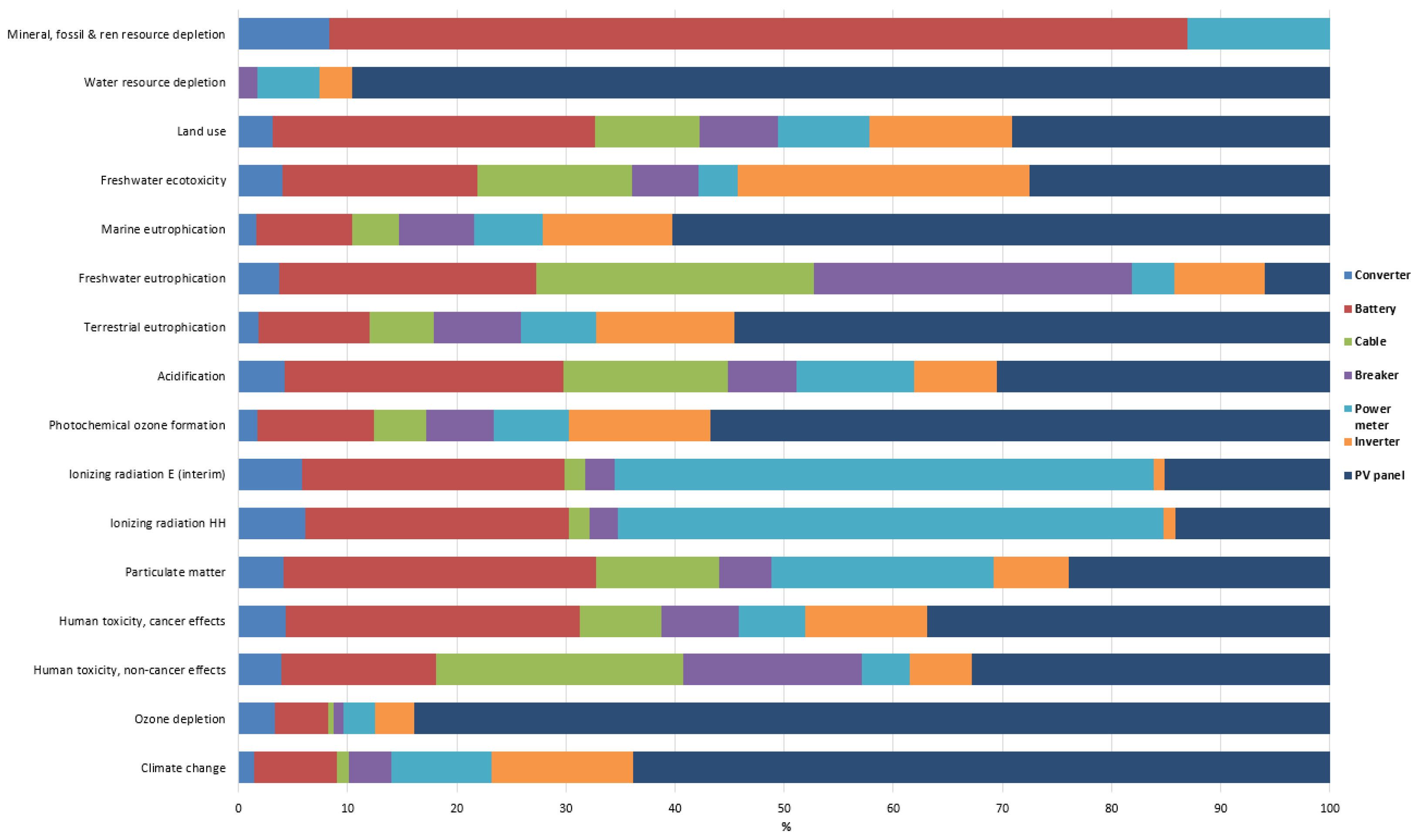
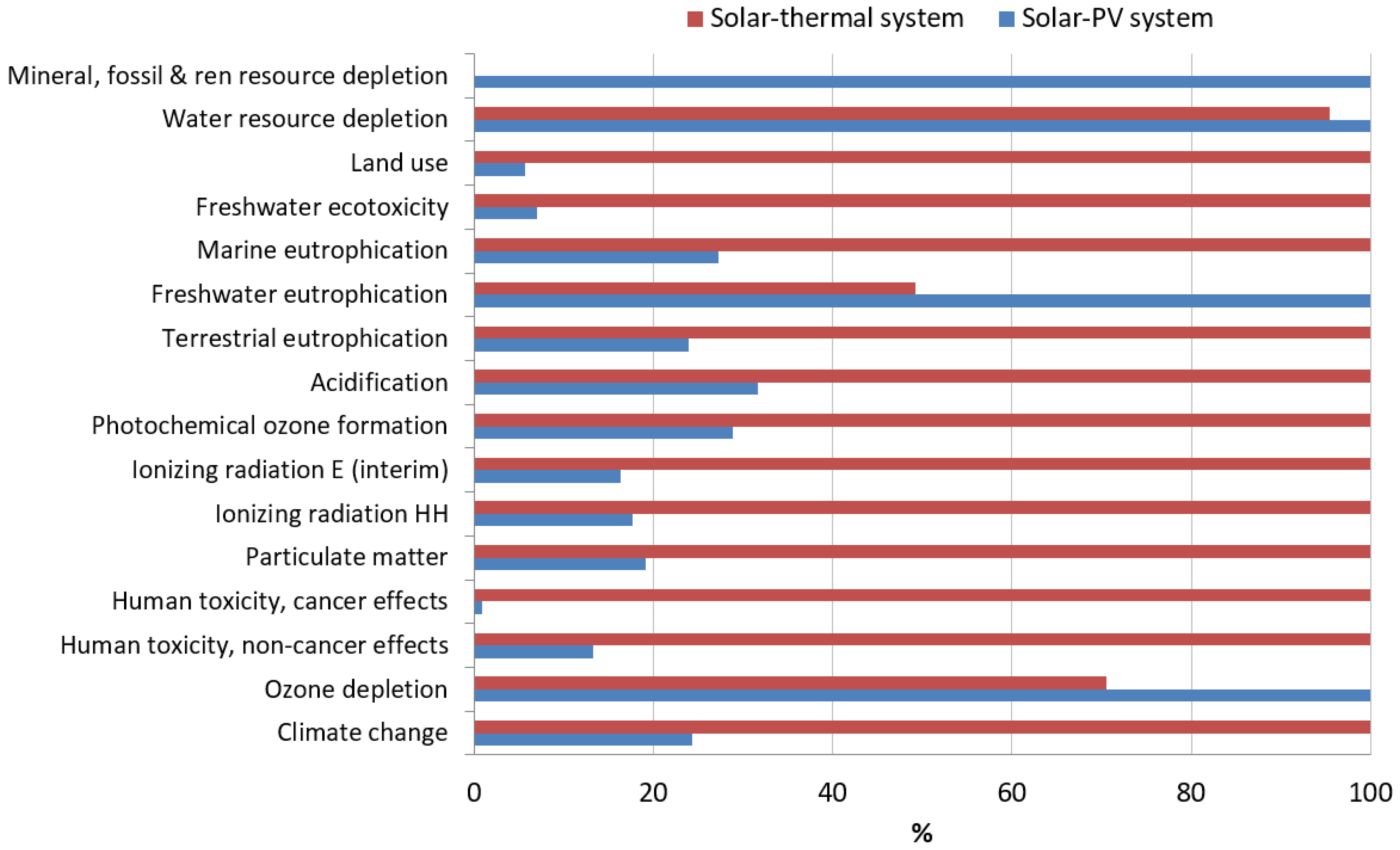
The life-cycle comparative environmental impacts of the solar PV and thermal systems are depicted in Figure 11, as estimated by the ILCD method. The results show that the solar-thermal system emits more hazardous materials and is highly responsible for more of the impact categories like land use, freshwater ecotoxicity, marine and terrestrial eutrophication, acidification, photochemical ozone formation, ionizing radiation, particulate matter, human toxicity and climate change than the solar-PV system.
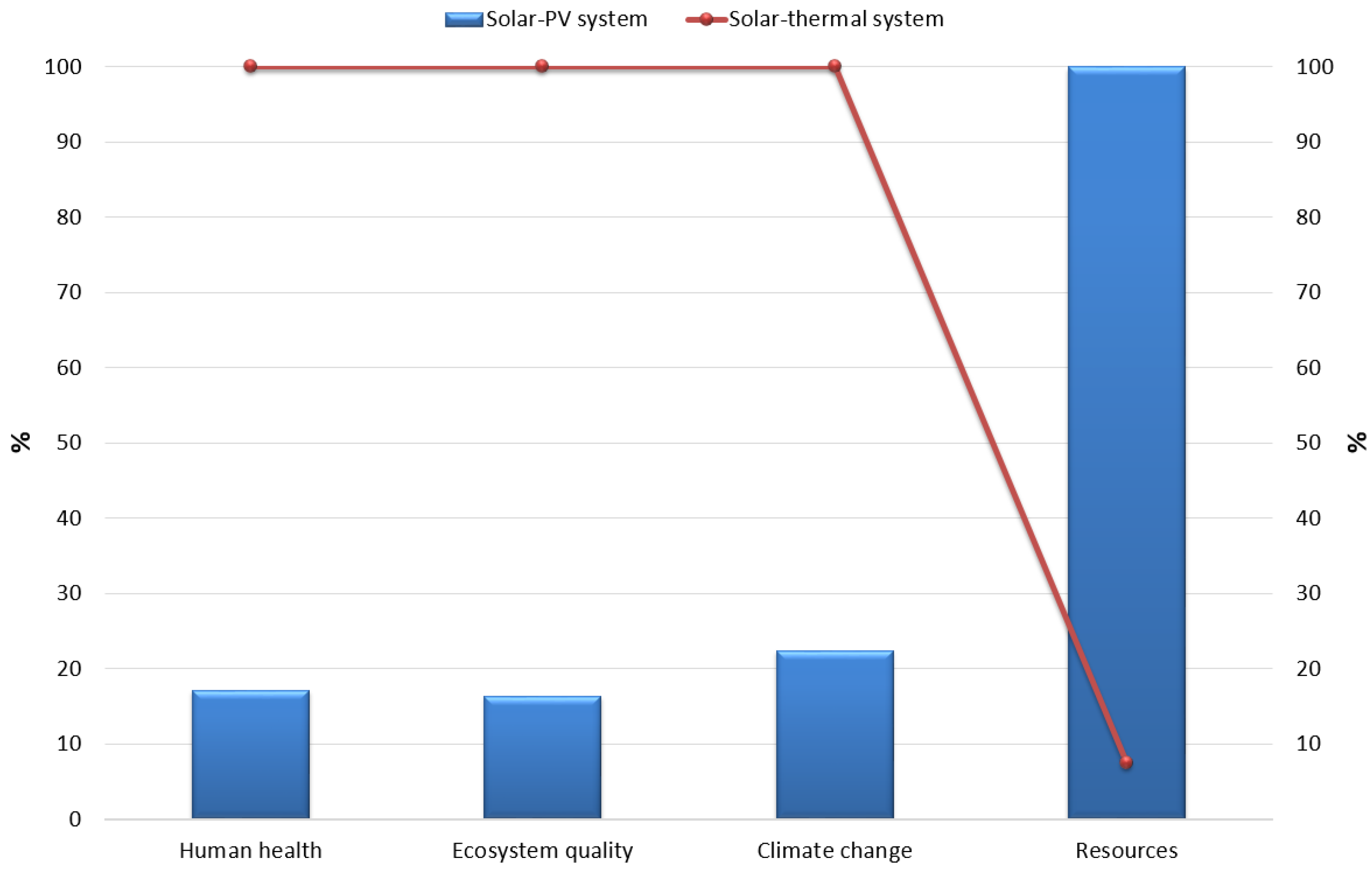
The cradle-to-grave effect outcome comparison between the solar PV and thermal frameworks is obtained by the Impact 2002+ method under four major indicators, as demonstrated in Figure 12. The outcome shows that the solar-thermal system is more dangerous for human health, climate change and the ecosystem than a solar-PV system of equivalent rate. However, the impacts to resources by the solar-PV system are ten times as high as for the solar-thermal framework.
3.4. GHG Emission Factor Estimation
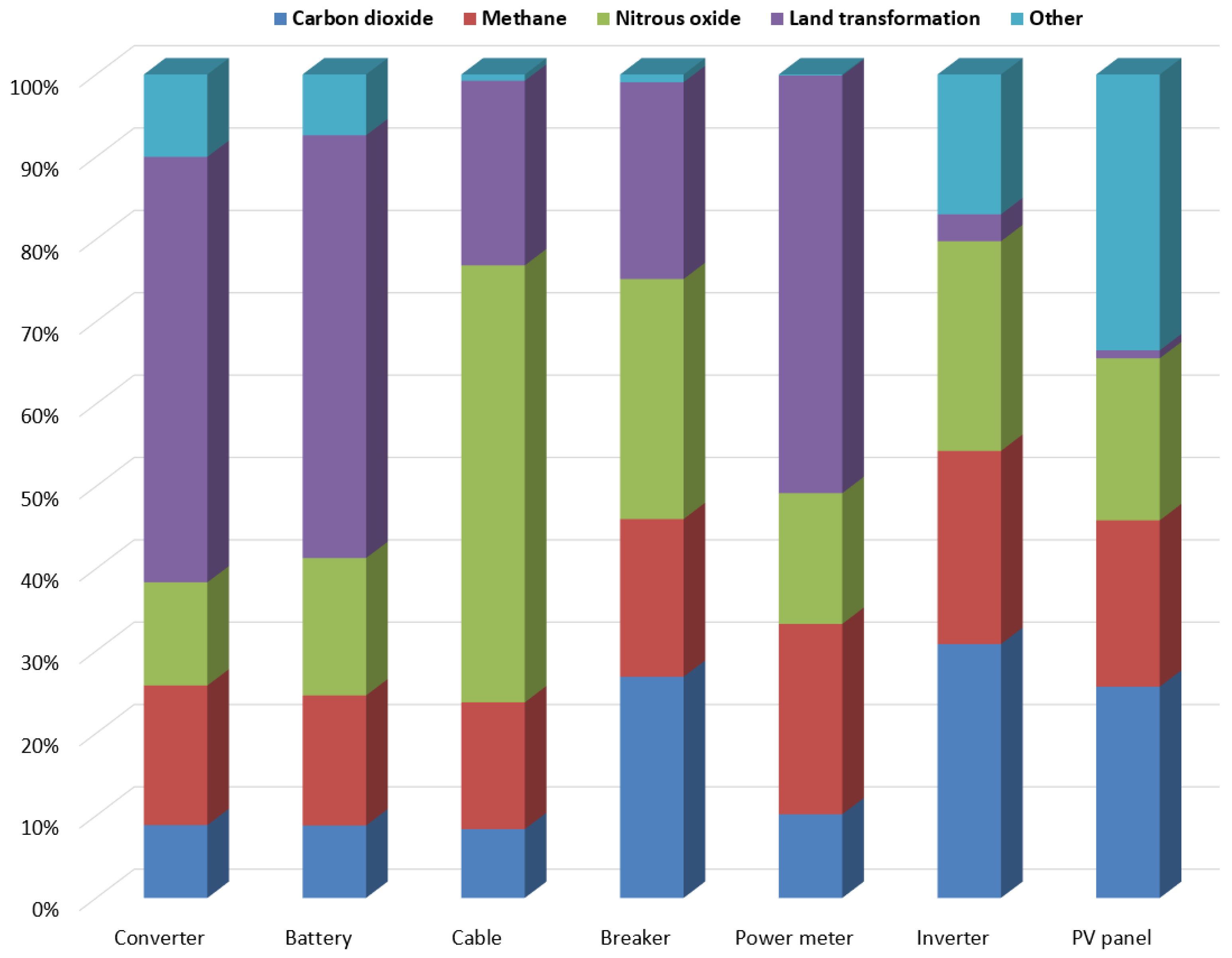
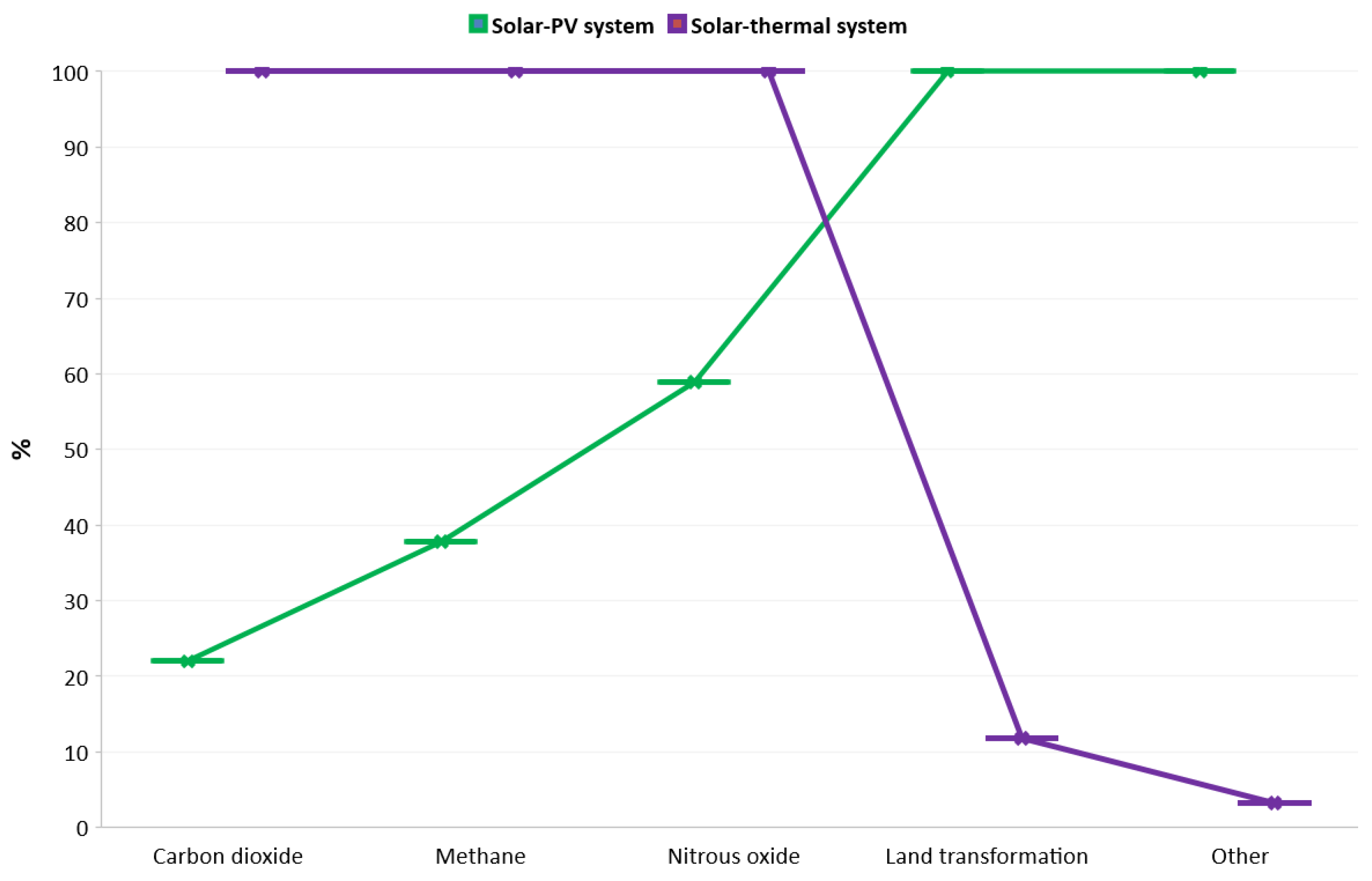
The well-known IPCC method [57] is used to evaluate and compare the greenhouse gas emissions of the solar PV and thermal systems. Figure 13 and Figure 14 show GHG releases by the solar-PV and thermal frameworks. Clearly, the maximum amount of dangerous nitrous oxide and carbon dioxide emission were the responsibility of the cable and inverter, respectively. However, the converter, battery and power meter are mostly responsible for land transformation. The valve, flow meter and HTF tank released the maximum to the land from the solar-thermal system. The solar collector, boiler, heat storage, temperature gauge of the solar-thermal system emitted a higher amount of nitrous oxide to the environment. The comparative GHG release obtained by the IPCC approach is demonstrated as Figure 15, which shows that solar-thermal framework releases about five times as much carbon dioxide as the solar-PV. The nitrous oxide emission is doubled for the solar-thermal system in comparison to the solar-PV. However, other GHGs were emitted mostly by the solar-PV system. Overall, the obtained outcomes of this research confirm that cautious selection of a less toxic solar panels, battery and heat storage is a prerequisite to achieve a superior environmental performance by both systems.
3.5. Fossil-Fuel-Based Energy Consumption Evaluation
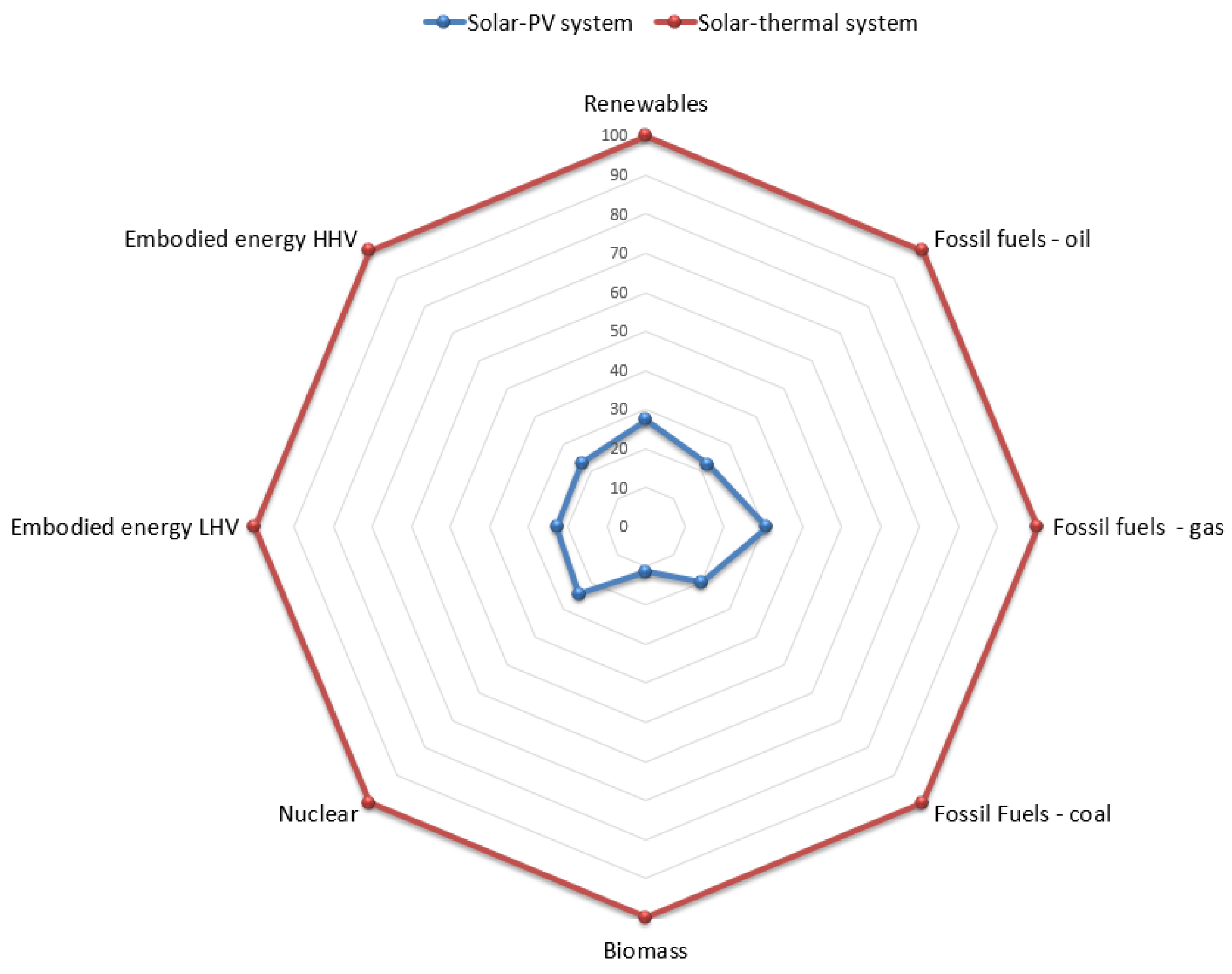
The comparative amounts of fossil-fuel-based energy consumption by the solar PV and thermal systems are demonstrated in Figure 16, which is found by the CED approach [54] of LCA. Clearly, the outcome shows that solar-thermal installations consume higher power than solar-PV systems. The gas-based fossil-fuel consumption rate is the maximum power usage by the solar-PV system. On the other hand, biomass-based energy is the lowest amount of energy consumption by the solar-PV framework. Therefore, regarding a smaller amount of fossil-fuel consumption, the solar-PV installation is a better choice than the solar-thermal installations.
3.6. Sensitivity and Uncertainty Analysis
Two sensitivity analyses have been conducted to examine the environmental performance of the solar-thermal systems and solar-PV systems for different PV panels and batteries to discover the superior one in terms of the environment. Table 5 reveals the impacts of a solar-thermal framework for five different solar collectors: Amorphous silicon (a-Si), Copper indium selenide (CIS), multi-Si, ribbon Si and single Si. The analysis outcome shows that single Si is highly accountable for climate change, whereas the CIS collector is the least hazardous to the climate. The solar collector made of a-Si is largely liable for human toxicity and the multi-Si-based collectors are mostly responsible for water resource depletion. Overall, the solar collectors made from CIS provided a superior environmental profile. Various types of batteries such as lithium-ion (Li-ion), sodium chloride (NaCl) and Nickel–metal hydride (NiMH) are used in the sensitivity analysis of a solar-PV framework.
The analysis outcome based on different battery types for the solar-PV system highlighted in Table 6 shows that a NiMH-based framework provides higher impacts for indicators like acidification, particulate matter, ozone depletion, ionizing radiation, eutrophication, freshwater toxicity, water resource depletion, and climate change. The NaCl-battery-based solar-PV system had a maximum for the human-toxicity category. Overall, the Li-ion type battery-based solar-PV framework showed the best environmental profile at the sensitivity analysis outcome. Therefore, stakeholders should consider CIS as a solar collector and a Li-ion battery as the energy storage device in building solar systems. The main implication of this result is in the solar-pv and solar-thermal plant industry, in which investors should use environmentally-friendly parts to reduce the environmental impacts.
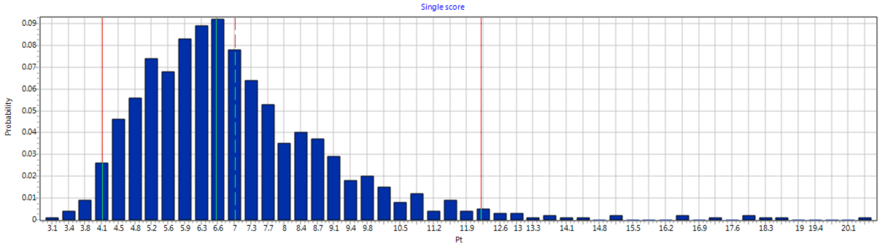
The probability distributions of the solar-PV and thermal systems are demonstrated in Figure 17 and Figure 18, which are obtained by using the Eco-Indicator 99 approach of LCA. The bars with smaller rate depict higher probabilities of getting identical impacts from the installations. The lower bars of the probability distributions for the single-score impact category of the solar-PV System with a rate of approximately 90% of the total probabilities indicate that this system is environmentally highly viable. Furthermore, about 70% of the small bars of the probability distributions for the single-score impact category of the solar-thermal system reveal that this system is also environment friendly and robust.
4. Limitations of This Study
The key limitations of this study are summarised as follows:
- The LCA of solar technologies other than solar-PV and solar-thermal have not been studied in this research.
- The LCA analysis of this study is completely dependent on the Ecoinvent 2.0 global database.
- Sensitivity analysis has been accomplished for the battery and the solar collector alone due to the lack of data sources.
- The replacement of elements that are responsible for hazardous emissions without considering the efficiencies and robustness of the systems has not been studied in this research.
- The ways to reduce the consumption of fossil-fuels during the manufacturing of elements, installation and operation of the systems, and the waste-management periods have not been tracked in this work.
- Determination of the energy payback period and an economic estimation of the considered solar systems have not been accomplished.
The future studies should be directed toward the overcoming of the above-mentioned limitations of this work. Thus, solar systems can eliminate many long-term dangerous emissions.
5. Conclusions
In this paper, the systematic LCA-based environmental effects of a solar-PV and a solar-thermal system are evaluated and compared. To assure the effectiveness of this research, (i) a comprehensive system boundary is developed for both of the considered solar technologies, (ii) a life-cycle assessment is carried out for both systems by multiple methods to assess the environmental profiles, (iii) the greenhouse gas emission rates are estimated for both of the systems, and (iv) a sensitivity and uncertainty analysis is conducted to examine the environmental performance of both systems more critically. The well-known SimaPro software and renowned Ecoinvent global database are used for assessing the life-cycle environmental impacts by multiple methods such as ILCD for mid-point analysis, Impact 2002+ for end-point analysis, CED for fossil-fuel-based energy consumption estimation, Eco-points 97 for metal and gas-based emission assessment, Eco-indicator 99 for uncertainty analysis and IPCC for GHG emission evaluation. The outcome of this research provides valuable information on the environmental impacts of each elements of the considered solar technologies and identifies the better environmentally-friendly option in the case of battery energy storage and solar collectors. The results highlight that the solar-PV framework performs environmentally superior than the solar-thermal framework for most of the impact indicators such as land use, freshwater ecotoxicity, marine and terrestrial eutrophication, acidification, photochemical ozone formation, ionizing radiation, particulate matter, human toxicity and climate change. The outcomes also reveal that the solar-PV system is less impactful for human health, climate change and the ecosystem than the solar-thermal system. Sensitivity analysis shows that CIS-solar collectors and Li-ion batteries perform better than others for the solar-thermal and solar-PV system, respectively. However, the main limitation of this work is that a sensitivity analysis for all considered elements has not been carried out. Thus, the future direction of this work is to track the unsafe components and check their possible replacements for more environmentally-friendly solar systems. Overall, it is recommended that, in order to protect the environment from hazardous emissions by the solar technologies, future research should be directed toward finding replacements for hazardous parts or processes by others that have a superior profile in terms of the environment.
Author Contributions
M.A.P.M. and N.H. conceived and designed the project; M.A.P.M. and S.H.F. performed the LCA simulations; N.H. and M.A.P.M. analyzed the outcome; C.L. contributed database and software management; M.A.P.M. and S.H.F. drafted the manuscript; N.H. and C.L. performed the overall supervision in this research.
Funding
This research received no external funding.
Acknowledgments
This work is part of a PhD research funded by Macquarie University’s iMQRTP scholarship scheme. The authors gratefully acknowledge the English editing service provided by Keith Imrie and the anonymous reviewers who helped in improving the manuscript.
Conflicts of Interest
The authors declare no conflict of interest. The founding sponsors had no role in the design of the study; in the collection, analyses, or interpretation of data; in the writing of the manuscript, and in the decision to publish the results.
References
- Righi, S.; Baioli, F.; Dal Pozzo, A.; Tugnoli, A. Integrating Life Cycle Inventory and Process Design Techniques for the Early Estimate of Energy and Material Consumption Data. Energies 2018, 11, 970. [Google Scholar] [CrossRef]
- Atilgan, B.; Azapagic, A. Assessing the Environmental Sustainability of Electricity Generation in Turkey on a Life Cycle Basis. Energies 2016, 9, 31. [Google Scholar] [CrossRef]
- Kommalapati, R.; Kadiyala, A.; Shahriar, M.T.; Huque, Z. Review of the Life Cycle Greenhouse Gas Emissions from Different Photovoltaic and Concentrating Solar Power Electricity Generation Systems. Energies 2017, 10, 350. [Google Scholar] [CrossRef]
- Dale, A.T.; Pereira de Lucena, A.F.; Marriott, J.; Borba, B.S.M.C.; Schaeffer, R.; Bilec, M.M. Modeling Future Life-Cycle Greenhouse Gas Emissions and Environmental Impacts of Electricity Supplies in Brazil. Energies 2013, 6, 3182–3208. [Google Scholar] [CrossRef] [Green Version]
- Murphy, D.J.; Carbajales-Dale, M.; Moeller, D. Comparing Apples to Apples: Why the Net Energy Analysis Community Needs to Adopt the Life-Cycle Analysis Framework. Energies 2016, 9, 917. [Google Scholar] [CrossRef]
- Mahmud, M.P.; Farjana, S.H. Design and Construction of Refrigerant Charge Level Detecting Device in HVAC/R System with Microcontroller. Int. J. Eng. Adv. Technol. (IJEAT) 2012, 1, 309–314. [Google Scholar]
- Amponsah, N.Y.; Troldborg, M.; Kington, B.; Aalders, I.; Hough, R.L. Greenhouse gas emissions from renewable energy sources: A review of lifecycle considerations. Renew. Sustain. Energy Rev. 2014, 39, 461–475. [Google Scholar] [CrossRef]
- Mahmud, M.P.; Lee, J.; Kim, G.; Lim, H.; Choi, K.B. Improving the surface charge density of a contact-separation-based triboelectric nanogenerator by modifying the surface morphology. Microelectron. Eng. 2016, 159, 102–107. [Google Scholar] [CrossRef]
- Lizin, S.; Van Passel, S.; De Schepper, E.; Maes, W.; Lutsen, L.; Manca, J.; Vanderzande, D. Life cycle analyses of organic photovoltaics: A review. Energy Environ. Sci. 2013, 6, 3136–3149. [Google Scholar] [CrossRef]
- Capellan-Perez, I.; Arto, I.; Polanco-Martinez, J.M.; Gonzalez-Eguino, M.; Neumann, M.B. Likelihood of climate change pathways under uncertainty on fossil fuel resource availability. Energy Environ. Sci. 2016, 9, 2482–2496. [Google Scholar] [CrossRef]
- El-Bialy, E.; Shalaby, S.; Kabeel, A.; Fathy, A. Cost analysis for several solar desalination systems. Desalination 2016, 384, 12–30. [Google Scholar] [CrossRef]
- Tamboli, A.C.; Bobela, D.C.; Kanevce, A.; Remo, T.; Alberi, K.; Woodhouse, M. Low-Cost CdTe/Silicon Tandem Solar Cells. IEEE J. Photovolt. 2017, 7, 1767–1772. [Google Scholar] [CrossRef]
- Farjana, S.H.; Huda, N.; Mahmud, M.P.; Saidur, R. Solar process heat in industrial systems-A global review. Renew. Sustain. Energy Rev. 2018, 82, 2270–2286. [Google Scholar] [CrossRef]
- Latunussa, C.E.; Ardente, F.; Blengini, G.A.; Mancini, L. Life Cycle Assessment of an innovative recycling process for crystalline silicon photovoltaic panels. Sol. Energy Mater. Sol. Cells 2016, 156, 101–111. [Google Scholar] [CrossRef]
- Gerbinet, S.; Belboom, S.; Leonard, A. Life Cycle Analysis (LCA) of photovoltaic panels: A review. Renew. Sustain. Energy Rev. 2014, 38, 747–753. [Google Scholar] [CrossRef]
- Espinosa, N.; Hosel, M.; Jorgensen, M.; Krebs, F.C. Large scale deployment of polymer solar cells on land, on sea and in the air. Energy Environ. Sci. 2014, 7, 855–866. [Google Scholar] [CrossRef] [Green Version]
- Espinosa, N.; Zimmermann, Y.S.; dos Reis Benatto, G.A.; Lenz, M.; Krebs, F.C. Outdoor fate and environmental impact of polymer solar cells through leaching and emission to rainwater and soil. Energy Environ. Sci. 2016, 9, 1674–1680. [Google Scholar] [CrossRef] [Green Version]
- Akinyele, D.; Belikov, J.; Levron, Y. Battery Storage Technologies for Electrical Applications: Impact in Stand-Alone Photovoltaic Systems. Energies 2017, 10, 1760. [Google Scholar] [CrossRef]
- Ardente, F.; Beccali, G.; Cellura, M.; Brano, V.L. Life cycle assessment of a solar thermal collector. Renew. Energy 2005, 30, 1031–1054. [Google Scholar] [CrossRef]
- Hou, J.; Zhang, W.; Wang, P.; Dou, Z.; Gao, L.; Styles, D. Greenhouse Gas Mitigation of Rural Household Biogas Systems in China: A Life Cycle Assessment. Energies 2017, 10, 239. [Google Scholar] [CrossRef]
- Atilgan, B.; Azapagic, A. Life cycle environmental impacts of electricity from fossil fuels in Turkey. J. Clean. Prod. 2015, 106, 555–564. [Google Scholar] [CrossRef]
- Mahmud, M.P.; Farjana, S.H. Wind Power Technology Schemes as Renewable Energy in Bangladesh. Int. J. Eng. Adv. Technol. (IJEAT) 2012, 1, 315–319. [Google Scholar]
- Ward, D.J.; Inderwildi, O.R. Global and local impacts of UK renewable energy policy. Energy Environ. Sci. 2013, 6, 18–24. [Google Scholar] [CrossRef]
- Das, P.D.D.; Srinivasan, P.R.; Sharfuddin, P.D.A. Fossil Fuel Consumption, Carbon Emissions and Temperature Variation in India. Energy Environ. 2011, 22, 695–709. [Google Scholar] [CrossRef]
- Rubio, L.M.; Filho, J.P.B.; Henriquez, J.R. Performance of a PV/T Solar Collector in a Tropical Monsoon Climate City in Brazil. IEEE Lat. Am. Trans. 2018, 16, 140–147. [Google Scholar] [CrossRef]
- Santoyo-Castelazo, E.; Gujba, H.; Azapagic, A. Life cycle assessment of electricity generation in Mexico. Energy 2011, 36, 1488–1499. [Google Scholar] [CrossRef]
- Jacobson, M.Z.; Delucchi, M.A.; Bazouin, G.; Bauer, Z.A.F.; Heavey, C.C.; Fisher, E.; Morris, S.B.; Piekutowski, D.J.Y.; Vencill, T.A.; Yeskoo, T.W. 100% clean and renewable wind, water, and sunlight (WWS) all-sector energy roadmaps for the 50 United States. Energy Environ. Sci. 2015, 8, 2093–2117. [Google Scholar] [CrossRef]
- Hou, G.; Sun, H.; Jiang, Z.; Pan, Z.; Wang, Y.; Zhang, X.; Zhao, Y.; Yao, Q. Life cycle assessment of grid-connected photovoltaic power generation from crystalline silicon solar modules in China. Appl. Energy 2016, 164, 882–890. [Google Scholar] [CrossRef]
- Boustead, I. General principles for life cycle assessment databases. J. Clean. Prod. 1993, 1, 167–172. [Google Scholar] [CrossRef]
- Gong, J.; Darling, S.B.; You, F. Perovskite photovoltaics: Life-cycle assessment of energy and environmental impacts. Energy Environ. Sci. 2015, 8, 1953–1968. [Google Scholar] [CrossRef]
- Stoppato, A. Life cycle assessment of photovoltaic electricity generation. Energy 2008, 33, 224–232. [Google Scholar] [CrossRef]
- Farjana, S.H.; Huda, N.; Mahmud, M.A.P.; Rahman, S. Solar Industrial Process Heating Systems in Operation—Current SHIP Plants and Future Prospects in Australia. Renew. Sustain. Energy Rev. 2018, 91, 409–419. [Google Scholar] [CrossRef]
- Arnaoutakis, N.; Souliotis, M.; Papaefthimiou, S. Comparative experimental Life Cycle Assessment of two commercial solar thermal devices for domestic applications. Renew. Energy 2017, 111, 187–200. [Google Scholar] [CrossRef]
- Masruroh, N.A.; Li, B.; Klemes, J. Life cycle analysis of a solar thermal system with thermochemical storage process. Renew. Energy 2006, 31, 537–548. [Google Scholar] [CrossRef]
- Nugent, D.; Sovacool, B.K. Assessing the lifecycle greenhouse gas emissions from solar PV and wind energy: A critical meta-survey. Energy Policy 2014, 65, 229–244. [Google Scholar] [CrossRef]
- Leccisi, E.; Raugei, M.; Fthenakis, V. The Energy and Environmental Performance of Ground-Mounted Photovoltaic Systems—A Timely Update. Energies 2016, 9, 622. [Google Scholar] [CrossRef]
- Sherwani, A.; Usmani, J.; Varun. Life cycle assessment of solar PV based electricity generation systems: A review. Renew. Sustain. Energy Rev. 2010, 14, 540–544. [Google Scholar] [CrossRef]
- Chow, T. A review on photovoltaic/thermal hybrid solar technology. Appl. Energy 2010, 87, 365–379. [Google Scholar] [CrossRef]
- Heijungs, R.; Guineev, J.B. An Overview of the Life Cycle Assessment Method–Past, Present, and Future. In Life Cycle Assessment Handbook; Wiley-Blackwell: Hoboken, NJ, USA, 2012; pp. 15–41. [Google Scholar]
- Farjana, S.H.; Huda, N.; Mahmud, M.P.; Lang, C. Towards sustainable TiO2 production: An investigation of environmental impacts of ilmenite and rutile processing routes in Australia. J. Clean. Prod. 2018, 196, 1016–1025. [Google Scholar] [CrossRef]
- Lewandowska, A.; Matuszak-Flejszman, A.; Joachimiak, K.; Ciroth, A. Environmental life cycle assessment (LCA) as a tool for identification and assessment of environmental aspects in environmental management systems (EMS). Int. J. Life Cycle Assess. 2011, 16, 247–257. [Google Scholar] [CrossRef] [Green Version]
- Keoleian, G.A. The application of life cycle assessment to design. J. Clean. Prod. 1993, 1, 143–149. [Google Scholar] [CrossRef]
- Pesso, C. Life cycle methods and applications: Issues and perspectives. J. Clean. Prod. 1993, 1, 139–142. [Google Scholar] [CrossRef]
- De Larderel, J.A. Environmental life cycle assessment and its applications. J. Clean. Prod. 1993, 1, 130–139. [Google Scholar] [CrossRef]
- Mahmud, M.A.P.; Huda, N.; Farjana, S.H.; Lang, C. Environmental sustainability assessment of hydropower plant in Europe using life cycle assessment. IOP Conf. Ser. Mater. Sci. Eng. 2018, 351, 012–018. [Google Scholar] [CrossRef]
- De Haes, H.A.U. Methodology and LCA applications. J. Clean. Prod. 1993, 1, 205–206. [Google Scholar] [CrossRef]
- Pryshlakivsky, J.; Searcy, C. Fifteen years of ISO 14040: A review. J. Clean. Prod. 2013, 57, 115–123. [Google Scholar] [CrossRef]
- Finkbeiner, M.; Inaba, A.; Tan, R.; Christiansen, K.; Klüppel, H.J. The New International Standards for Life Cycle Assessment: ISO 14040 and ISO 14044. Int. J. Life Cycle Assess. 2006, 11, 80–85. [Google Scholar] [CrossRef]
- Stavropoulos, P.; Giannoulis, C.; Papacharalampopoulos, A.; Foteinopoulos, P.; Chryssolouris, G. Life Cycle Analysis: Comparison between Different Methods and Optimization Challenges. Proc. CIRP 2016, 41, 626–631. [Google Scholar] [CrossRef]
- Pascual-González, J.; Guillén-Gosálbez, G.; Mateo-Sanz, J.M.; Jiménez-Esteller, L. Statistical analysis of the ecoinvent database to uncover relationships between life cycle impact assessment metrics. J. Clean. Prod. 2016, 112, 359–368. [Google Scholar] [CrossRef]
- Frischknecht, R.; Rebitzer, G. The ecoinvent database system: A comprehensive web-based LCA database. J. Clean. Prod. 2005, 13, 1337–1343. [Google Scholar] [CrossRef]
- Jolliet, O.; Margni, M.; Charles, R.; Humbert, S.; Payet, J.; Rebitzer, G.; Rosenbaum, R. IMPACT 2002+: A new life cycle impact assessment methodology. Int. J. Life Cycle Assess. 2003, 8, 324. [Google Scholar] [CrossRef]
- Mancini, L.; Benini, L.; Sala, S. Resource footprint of Europe: Complementarity of material flow analysis and life cycle assessment for policy support. Environ. Sci. Policy 2015, 54, 367–376. [Google Scholar] [CrossRef]
- Rohrlich, M.; Mistry, M.; Martens, P.N.; Buntenbach, S.; Ruhrberg, M.; Dienhart, M.; Briem, S.; Quinkertz, R.; Alkan, Z.; Kugeler, K. A method to calculate the cumulative energy demand (CED) of lignite extraction. Int. J. Life Cycle Assess. 2000, 5, 369–373. [Google Scholar] [CrossRef]
- Cherni, J.A.; Olalde Font, R.; Serrano, L.; Henao, F.; Urbina, A. Systematic Assessment of Carbon Emissions from Renewable Energy Access to Improve Rural Livelihoods. Energies 2016, 9, 1086. [Google Scholar] [CrossRef]
- Neri, E.; Cespi, D.; Setti, L.; Gombi, E.; Bernardi, E.; Vassura, I.; Passarini, F. Biomass Residues to Renewable Energy: A Life Cycle Perspective Applied at a Local Scale. Energies 2016, 9, 922. [Google Scholar] [CrossRef]
- Liu, S.-Q.; Mao, X.-Q.; Gao, Y.-B.; Xing, Y.-K. Life Cycle Assessment, Estimation and Comparison of Greenhouse Gas Mitigation Potential of New Energy Power Generation in China. Adv. Clim. Chang. Res. 2012, 3, 147–153. [Google Scholar]
Figure 1.
Schematic framework of the solar-PV system.

Figure 2.
Schematic framework of the solar-thermal system.

Figure 3.
Step-by-step energy and material flows for both systems.

Figure 4.
System boundary of the life-cycle assessment (LCA).

Figure 5.
Life-cycle inputs and outputs of the solar-PV system using Raw Materials Flow methodology.
Figure 5.
Life-cycle inputs and outputs of the solar-PV system using Raw Materials Flow methodology.

Figure 6.
Environmental profiles of the considered solar-PV system.

Figure 7.
Endpoint impacts of the individual components of the solar-PV system.

Figure 8.
Life-cycle inputs and outputs of the solar-thermal system using Raw Materials Flow methodology.
Figure 8.
Life-cycle inputs and outputs of the solar-thermal system using Raw Materials Flow methodology.

Figure 9.
Environmental profiles of the considered solar-thermal system.

Figure 10.
Endpoint impacts of the individual components of the solar-thermal system.

Figure 11.
Comparison of environmental impacts from the solar-PV and the solar-thermal system.

Figure 12.
Endpoint impact comparison of the systems using Impact 2002+ methodology.

Figure 13.
Greenhouse gas (GHG) emission of the solar-PV system with a time period of 100 years.

Figure 14.
GHG emission of the solar-thermal system with a time period of 100 years.

Figure 15.
GHG emission comparison of the systems using Intergovernmental Panel on Climate Change (IPCC) methodology.
Figure 15.
GHG emission comparison of the systems using Intergovernmental Panel on Climate Change (IPCC) methodology.

Figure 16.
Comparative required energy from different sources to build, operate and waste management of both the systems.
Figure 16.
Comparative required energy from different sources to build, operate and waste management of both the systems.

Figure 17.
Probability distribution for the single-score impact category of the Solar-PV System.

Figure 18.
Probability distribution for the single-score impact category of the solar-thermal system.
Figure 18.
Probability distribution for the single-score impact category of the solar-thermal system.


Table 1.
Previous studies of life cycle assessment of solar-thermal system and their limitations.
| Source Ref. | Topic | Main Focus of the Work | Limitations |
|---|---|---|---|
| [19] | Life cycle assessment of a solar thermal collector. | The environmental performances of solar thermal collector for sanitary warm water demand has been studied. | Data source is not global. It is only applicable for the plants of Italy. |
| [25] | Performance of a PV/T Solar Collector in a Tropical Monsoon Climate City in Brazil. | This work identifies the most important parameters that affect the efficiency of the collector when operating in a locality of tropical monsoon climate zone in Brazil. | The estimation of step by step greenhouse gas (GHG) emission has not been undertaken. |
| [33] | Comparative experimental Life Cycle Assessment of two commercial solar thermal devices for domestic applications. | The environmental analysis for Flat Plate Thermos-phonic Units (FPTU) and Integrated Collector Storage (ICS) solar water heaters is carried out through a Life Cycle Assessment (LCA) study. | They have not considered the end-of-life phase in assessing the impacts. |
| [34] | Life cycle analysis of a solar thermal system with thermochemical storage process. | The LCA technique to study the environmental impacts associated with solar thermal system (SOLARSTORE) is highlighted in this work. The raw material acquisition and components manufacturing processes contribute 99% to the total environmental impacts during the whole life cycle. | The installation and maintenance processes are excluded from LCA. |
Table 2.
Previous studies of life cycle assessment of solar-PV system and their limitations.
| Source Ref. | Topic | Main Focus of the Work | Limitations |
|---|---|---|---|
| [3] | Review of the Life Cycle Greenhouse Gas Emissions from Different Photovoltaic and Concentrating Solar Power Electricity Generation Systems. | The cadmium telluride PVs and solar pond concentrated solar powers (CSPs) contributed to minimum life cycle GHGs. | The environmental contributions from the solar chimney and solar pond electricity generation systems has not been revealed. |
| [9] | Life cycle analyses of organic photovoltaics: a review. | Discussed the environmental impacts of organic photovoltaics (PVs) under several indicators like cumulative energy demand (CED), energy payback time (EPBT), and greenhouse gas (GHG) emission factor. | Lack of the evolution of environmental sustainability assessment in case of organic PVs. |
| [14] | Life Cycle Assessment of an innovative recycling process for crystalline silicon photovoltaic panels. | It analysed an innovative process for the recycling of silicon PV panel. | The end-of-life phase has been neglected in this analysis. |
| [15] | Life Cycle Analysis (LCA) of photovoltaic panels: A review. | It examined the energy-related indicators such as EPBT and the indicators relative to climate change such as CO emissions. | The electronic properties of the panel or balance of system (BOS) components has not been evaluated. |
| [28] | Life cycle assessment of grid-connected photovoltaic power generation from crystalline silicon solar modules in China. | Regardless multi-Si, mono-Si, large scale photovoltaic (LS-PV) or distributed PV system, PV station manufacturing is responsible for about 84% or even more of total energy consumption and GHG emissions. | The solution to cut down the energy consumption and GHG emission during PV station manufacturing has not been discussed. |
| [30] | Perovskite photovoltaics: life-cycle assessment of energy and environmental impacts. | Compared the results of Eco-indicator 99, the EPBT, and the CO emission factor among existing PV technologies, and further perform uncertainty analysis and sensitivity analysis for the two modules. | The way to lower the CO emission factor has not been mentioned and this work lacks information to improve the system performance ratio and the device lifetime. |
| [35] | Assessing the lifecycle greenhouse gas emissions from solar PV and wind energy: A critical meta-survey. | Physical characteristics of the solar technologies are most responsible for emissions. | The procedure to lower the greenhouse gas emission has not been highlighted. |
| [36] | The Energy and Environmental Performance of Ground-Mounted Photovoltaic Systems -A Timely Update | One-axis tracking installations of solar modules can improve the environmental profile of PV systems by approximately 10% for most impact metrics. | The benefits of employing a tracking BOS has not been explored. |
Table 3.
Data collection for frameworks in the solar-PV system and the solar-thermal system.
| Assembly | Unit Process | Process Source |
|---|---|---|
| Solar-PV system | Converter | Converter, 500 W, for electric system {GLO}/production/Conseq, U |
| Battery | Battery, Li-ion,rechargeable, prismatic {GLO}/market for/Alloc Def, U | |
| Cable | Cable, unspecified, {GLO}/market for/Conseq, U | |
| Breaker | Switch, toggle,type, at plant/GLO U/AusSD U | |
| Power meter | Electric meter,unspecified {GLO}/production/Conseq, U | |
| Inverter | Inverter, 500 W, at,plant/GLO U/I U/AusSD U | |
| PV panel | Photovoltaic panel,single-Si, at plant/GLO U/I U/AusSD U | |
| Solar-thermal system | Reservoir | Tap water, at user/RER U/AusSD U/Link U |
| Valve | Exhaust air valve, {GLO}/ production / Conseq, U | |
| Boiler | Hot water tank 200 L, at plant/GLO U /I U/AusSD U | |
| Solar collector | Solar collector glass tube, with silver mirror, at plant/GLO U/AusSD U | |
| Heat storage | Heat storage 200 L, at plant/GLO U/I U/AusSD U | |
| Temp. gauge | Temperature, 500 Degrees F gauge {GLO}/market for/Conseq, U | |
| Pump | Pump 40 W, at plant/GLO U/I U /AusSD U | |
| HTF tank | Expansion vessel 200 L, at plant /GLO U/I U/AusSD U | |
| Flow meter | Flow meters, vortex type, at plant /GLO U/AusSD U |
Table 4.
Life-cycle inputs and outputs comparison between the solar-PV system and the solar-thermal system.
Table 4.
Life-cycle inputs and outputs comparison between the solar-PV system and the solar-thermal system.
| Label | Solar-PV System (%) | Solar-Thermal System (%) |
|---|---|---|
| Inputs from nature | 20.80 | 100 |
| Outputs to air | 23.26 | 100 |
| Outputs to water | 100 | 0.43 |
| Outputs to soil | 27.48 | 100 |
| Outputs solid waste | 35.15 | 100 |
Table 5.
Sensitivity analysis outcome based on different solar collector types for the solar-thermal system.
Table 5.
Sensitivity analysis outcome based on different solar collector types for the solar-thermal system.
| Impact Category | a-Si [mPt] | CIS [mPt] | Multi-Si [mPt] | Ribbon-Si [mPt] | Single-Si [mPt] |
|---|---|---|---|---|---|
| Climate change | 0.31 | 0.13 | 1.86 | 1.62 | 2.55 |
| Ozone depletion | 0.002 | 0.001 | 0.18 | 0.17 | 0.1837 |
| Human toxicity, cancer effects | 9.71 | 1.56 | 8.46 | 3.76 | 8.90 |
| Particulate matter | 0.11 | 0.03 | 0.61 | 0.51 | 0.707 |
| Ionizing radiation-Human Health (HH) | 0.09 | 0.03 | 0.16 | 0.12 | 0.156 |
| Ionizing radiation-Ecosystem (E) | 0.19 | 0.13 | 0.14 | 0.35 | 0.527 |
| Photochemical ozone formation | 0.10 | 0.04 | 1.01 | 0.92 | 1.28 |
| Acidification | 0.10 | 0.04 | 0.67 | 0.59 | 0.835 |
| Terrestrial eutrophication | 0.10 | 0.04 | 0.80 | 0.71 | 1.105 |
| Freshwater eutrophication | 0.001 | 0.002 | 0.09 | 0.09 | 0.094 |
| Marine eutrophication | 0.05 | 0.02 | 0.47 | 0.43 | 0.649 |
| Freshwater ecotoxicity | 0.41 | 0.09 | 1.68 | 1.50 | 1.767 |
| Land use | 9.9 | 3.7 | 5.1 | 4.2 | 5.9 |
| Water resource depletion | 0.06 | 0.02 | 3.28 | 1.50 | 2.94 |
| Mineral, fossil & renewable resource depletion | 5.16 | 4.95 | 1.23 | 9.36 | 1.2 |
Table 6.
Sensitivity analysis outcome based on different battery types for the solar-PV system.
| Impact Category | Li-ion [mPt] | NaCl [mPt] | NiMH [mPt] |
|---|---|---|---|
| Climate change | 0.0559 | 0.0558 | 0.1813 |
| Ozone depletion | 0.0072 | 0.0053 | 0.5297 |
| Human toxicity, non-cancer effects | 1.8839 | 1.3667 | 1.093 |
| Human toxicity, cancer effects | 1.0477 | 2.6478 | 2.2411 |
| Particulate matter | 0.123 | 0.455 | 1.045 |
| Ionizing radiation-Human Health (HH) | 0.068 | 0.174 | 0.174 |
| Ionizing radiation-Ecosystem (E) | 0.015 | 0.227 | 0.871 |
| Photochemical ozone formation | 0.040 | 0.092 | 0.208 |
| Acidification | 0.114 | 0.757 | 1.753 |
| Terrestrial eutrophication | 0.037 | 0.044 | 0.092 |
| Freshwater eutrophication | 0.058 | 0.045 | 0.054 |
| Marine eutrophication | 0.017 | 0.019 | 0.041 |
| Freshwater ecotoxicity | 0.258 | 0.260 | 0.383 |
| Land use | 0.00049 | 0.00051 | 0.00084 |
| Water resource depletion | 0.287 | 0.658 | 0.912 |
| Mineral, fossil & renewable resource depletion | 0.806 | 0.670 | 2.111 |
© 2018 by the authors. Licensee MDPI, Basel, Switzerland. This article is an open access article distributed under the terms and conditions of the Creative Commons Attribution (CC BY) license (http://creativecommons.org/licenses/by/4.0/).
Share and Cite
MDPI and ACS Style
Mahmud, M.A.P.; Huda, N.; Farjana, S.H.; Lang, C. Environmental Impacts of Solar-Photovoltaic and Solar-Thermal Systems with Life-Cycle Assessment. Energies 2018, 11, 2346. https://doi.org/10.3390/en11092346
AMA Style
Mahmud MAP, Huda N, Farjana SH, Lang C. Environmental Impacts of Solar-Photovoltaic and Solar-Thermal Systems with Life-Cycle Assessment. Energies. 2018; 11(9):2346. https://doi.org/10.3390/en11092346
Chicago/Turabian StyleMahmud, M. A. Parvez, Nazmul Huda, Shahjadi Hisan Farjana, and Candace Lang. 2018. "Environmental Impacts of Solar-Photovoltaic and Solar-Thermal Systems with Life-Cycle Assessment" Energies 11, no. 9: 2346. https://doi.org/10.3390/en11092346
Note that from the first issue of 2016, this journal uses article numbers instead of page numbers. See further details here.